

 English
  русский
  Español
  عربى
عربى 
Content
- 1 Gas Springs Are Force-Adjustable, Lifespan-Limited Components
- 2 1. Core Functional Principles and Real-World Force Behaviour
- 3 2. Service Life, Deterioration, and the 20% Rule
- 4 3. Sizing, Force Calculation, and Selection Pitfalls
- 5 4. Maintenance, Monitoring, and Replacement Indicators
- 6 5. Special Variants: Lockable, Damping, and Stainless Steel
- 7 6. Safety Factors and Installation Best Practices
- 8 7. Summary – Practical Takeaways for Longevity
How to select the correct gas spring force for your application?
2026-07-22
Gas Springs Are Force-Adjustable, Lifespan-Limited Components
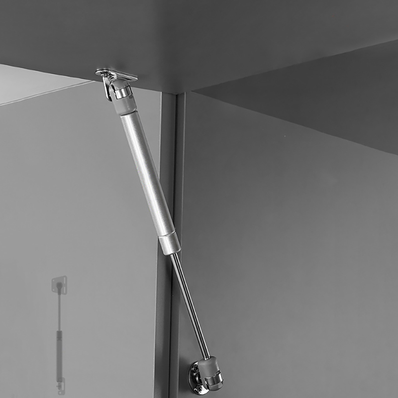
A gas spring is a mechanical device that uses compressed nitrogen gas to exert a controlled, nearly constant force over a defined stroke length. The fundamental answer is this: gas springs are not eternal; they are engineered consumables with a finite service life, typically 10,000 to 30,000 full cycles depending on operating conditions. Their core value lies in their ability to provide smooth, progressive support and dampening, but they are not a “fit-and-forget” component. Proper selection, mounting orientation, and regular force verification are the keys to maximising their useful life. This article provides a practical, data-driven guide to understanding, selecting, and maintaining gas springs for engineering, industrial, and furniture applications.
1. Core Functional Principles and Real-World Force Behaviour
At the heart of every gas spring is a piston rod moving within a sealed cylinder containing nitrogen gas and a small amount of oil. The gas is compressed as the rod is pushed in, creating a counterforce. The extension force (F1) is the force the spring exerts when fully extended, while the compression force (F2) is measured during stroke. The force progression curve is relatively flat, but not entirely constant. Most high-quality gas springs exhibit a force increase of only 10–15% from extended to compressed position, which is far smoother than a mechanical coil spring.
A critical yet often overlooked factor is the temperature sensitivity. Nitrogen gas obeys the ideal gas law; for every 10°C increase in ambient temperature, the internal pressure rises by approximately 3.5%. This translates to a direct force increase of 3–4% per 10°C. In real-world scenarios, a gas spring rated at 500 N at 20°C will deliver roughly 540 N at 60°C – a difference that can affect mechanism balance or safety. Therefore, always specify the operating temperature range and, if necessary, opt for temperature-compensated designs.
Practical example: In a hatchback tailgate, two gas springs of 400 N each are typically used. If the vehicle is parked in direct sunlight on a 35°C day, the internal temperature may reach 50°C, increasing each spring’s force to ~420 N. The combined extra 40 N may cause the tailgate to open more abruptly than designed, potentially stressing hinges.
2. Service Life, Deterioration, and the 20% Rule
The most frequent question engineers ask is: “How long will this gas spring last?” The standard industry benchmark is 20,000 cycles at room temperature with a 20% allowable force drop. After that point, the spring is considered worn. However, real-world longevity is governed by a triad of factors: rod surface quality, seal integrity, and side-loading. Side-loading – off-axis force – is the primary killer of gas springs. A side load of just 5% of the rated force can reduce service life by up to 40%.
The table below shows typical life expectancy under different operating conditions. These figures are based on aggregated field data from industrial and automotive applications.
| Condition | Clean, dry, 20°C | Humid, salty (marine) | With minor side-load (<3%) |
| Life (cycles) | 22,000 – 28,000 | 10,000 – 14,000 | 12,000 – 16,000 |
| Reduction vs. ideal | – | ~45–50% | ~40–45% |
To extend life, always mount the spring so that the rod faces downward (or slightly inclined) when in static rest. This allows the internal oil to lubricate the rod seal, reducing friction and wear. Conversely, rod-up orientation accelerates oil drainage and increases seal abrasion, cutting life by an estimated 15–25%.
3. Sizing, Force Calculation, and Selection Pitfalls
Selecting the correct gas spring is not a matter of guessing. The required force is determined by the weight of the lid/hatch, its centre of gravity, and the mounting geometry. The formula F = (W × L) / (n × d) is a good starting point, where W is the weight of the moving part, L is the horizontal distance from pivot to centre of gravity, n is the number of springs, and d is the distance from pivot to spring attachment point. A common error is oversizing – choosing a spring with 20% higher force than calculated often leads to a “kick” effect and accelerated seal wear.
Equally important is the stroke length. The spring should be chosen so that its extended length is approximately 5–10% longer than the fully open distance, ensuring that the internal piston does not bottom out. Bottoming out creates hydraulic lock and can permanently damage the internal damping system.
Selection checklist
- Determine required extension force (F1) with a safety margin of ±5%.
- Measure stroke length and add 10 mm clearance.
- Verify operating temperature range; derate force by 0.35%/°C if needed.
- Choose rod material (chrome-plated steel vs. stainless) for environment.
- Check connector types – eyelet, threaded, or ball stud.
Common mistakes
- Selecting force based on static load only (ignore dynamic effects).
- Mounting springs with incorrect rod orientation.
- Ignoring the end‑of‑stroke damping requirement.
- Using a single spring for wide lids – side-load risk increases.
4. Maintenance, Monitoring, and Replacement Indicators
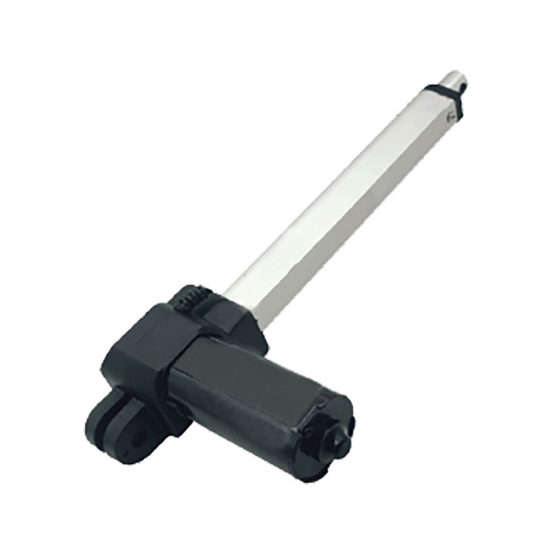
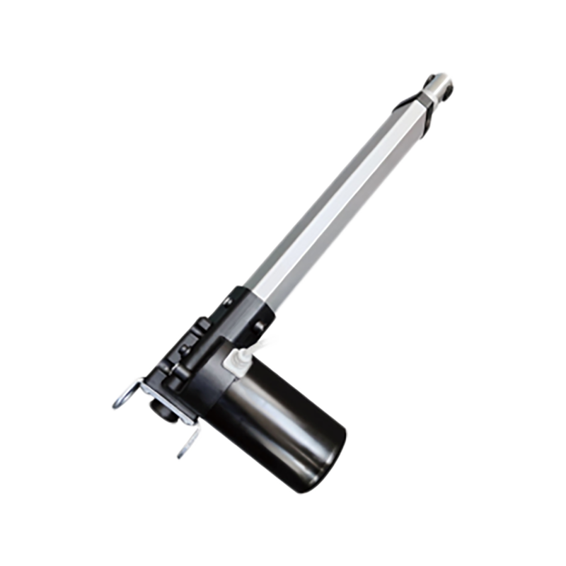
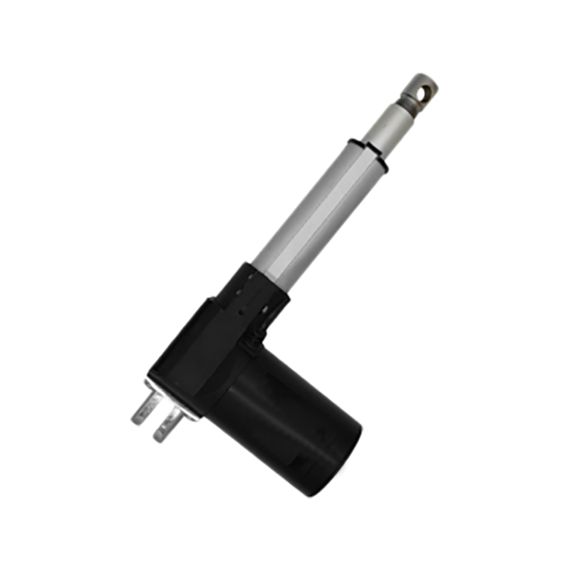
Unlike electric actuators, gas springs give little warning before failure. However, there are three tell‑tale signs: (1) a “spongy” or jerky motion, (2) visible oil leakage on the rod, and (3) a measurable force drop of more than 15% from the original specification. A simple field test involves using a force gauge to measure the extension force at the mid‑stroke point. If the force is below 85% of the rated value, replacement is due.
Preventive maintenance is often neglected. A bi‑annual wipe of the piston rod with a clean, lint‑free cloth removes abrasive particles that can score the surface. For heavy‑duty applications (e.g., agricultural machinery), consider a grease‑filled version with a scraper seal, which can extend life up to 40,000 cycles. Also, never exceed the maximum extension speed – most gas springs are rated for 0.3–0.5 m/s. Faster motion causes the internal oil to foam, reducing damping efficiency and accelerating seal degradation.
- Visual inspection – check for rod scratches, pitting, or rust.
- Force measurement – compare with original data plate (if available).
- Cycle test – extend and compress slowly, feel for stiction or chatter.
- Temperature check – if the body is unusually hot (>65°C), gas pressure may be excessive.
5. Special Variants: Lockable, Damping, and Stainless Steel
Beyond the standard free‑extending gas spring, there are specialised versions that address unique requirements. Lockable gas springs incorporate a valve mechanism that stops the piston at any position – ideal for height‑adjustable office chairs or medical tables. They provide infinite positioning but typically have a lower stroke‑to‑length ratio. Damping‑end gas springs feature an integrated oil damper in the final 10–15 mm of compression, cushioning the closure and reducing noise – commonly used in car boot lids.
For corrosive environments (marine, chemical plants), stainless steel 316 gas springs are available. They cost roughly 60–80% more than standard zinc‑plated versions but offer three to four times the corrosion resistance. The trade‑off is a slightly lower maximum force per diameter due to material properties. In food processing, gas springs with FDA‑approved oil and special sealing are mandatory. Always match the spring construction to the environmental exposure, not just the mechanical load.
6. Safety Factors and Installation Best Practices
Never forget that a gas spring stores energy. The internal pressure can exceed 150 bar (15 MPa) in heavy‑duty models. Use protective sleeves or containment tubes in applications where sudden rod ejection would pose a hazard. Additionally, the mounting brackets must withstand not only the static force but also the dynamic peak during opening and closing – typically 1.4 times the rated force.
A good practice is to install gas springs in pairs for wide or asymmetrical loads. This balances the moment and reduces side‑load on each spring. When installing, use a torque wrench on the threaded connections; overtightening can distort the cylinder body, causing internal friction. The recommended torque for M8 threads is 18–22 Nm; for M10, 35–40 Nm.
7. Summary – Practical Takeaways for Longevity
The actionable conclusion from this deep dive is that gas spring performance is predictable, but only if the user respects the force‑temperature‑life triangle. A spring operating at 70°C for a prolonged period will lose gas pressure at a rate approximately 2.5 times faster than at 20°C. Therefore, for high‑temperature environments, either derate the force requirement or use a spring with a higher initial charge.
Final recommendation: Plan for replacement every 5–7 years for indoor furniture, every 3–5 years for automotive external applications, and every 2–3 years for industrial machinery with high cycle rates. Keep a maintenance log with force measurement records – this data is invaluable for predictive maintenance schedules and minimising downtime.


- Contact Info
-
-
 Phone+86-15950656125
 -
 Email
Email -
 AddressRoom 1007-1, South Building, Suyue Plaza, Suzhou Industrial Park, Suzhou City, Jiangsu Province, China
-
- Products
- Follow Us
- Need help? Please contact us
Copyright ©
SuZhou Skyhone Intelligent Technology Co., Ltd.
All Rights Reserved.
Privacy
Custom Ergonomic Adjustable Office Tables Manufacturers

